

Addressing Mass Timber Floor Vibration in Complex Building Types
While there are many benefits to mass timber floors, their high strength-to-weight ratio make it easier for them to vibrate. Addressing these vibration issues in many building types is relatively straightforward. However, using mass timber floors in laboratories and hospitals is more challenging due to the stringent vibration criteria required for sensitive equipment and specialized activities. This article shares some of the creative design and engineering solutions that can address vibration, so that the many benefits of mass timber can be realized across additional building types in the future.
The Benefits of Mass Timber Floors
The lightness of mass timber for floors offers many advantages.
- Gravity Loads: Reduced gravity loads lessen demands on both the gravity system and foundations — an important benefit on poor soil sites.
- Carbon Footprint and Costs: Lowers the carbon footprint and transportation costs, while making on-site installation easier.
- Seismic Forces: Reduces lateral seismic loads which is especially valuable in high seismic regions.
- Vertical Additions: For vertical additions, this reduced weight can make it possible to add more floors without exceeding the capacity of the existing structure.
To date, mass timber has been predominantly applied in commercial, educational, and increasingly, high-rise residential and office buildings. Their use in laboratories and hospitals requires careful attention to vibration control issues.
Material Factors in Floor Performance
Understanding the interplay of mass, stiffness, and damping is essential when designing mass timber floors that must meet both comfort-based and equipment-driven vibration performance criteria. While mass timber systems have proven successful in many applications, achieving reliable vibration control — particularly in laboratory environments — requires deliberate tuning of these three parameters.
Mass
Heavier floors generally perform better in terms of vibration performance; however, the relationship between mass and vibration is not straightforward. While increased mass reduces sensitivity to walking induced excitation, it also lowers the floor’s natural frequency. If this frequency aligns with common walking-induced excitation frequencies, it will inadvertently increase the risk of resonance — causing the floor to become more susceptible to vibration and reducing overall performance.
In practice, engineers are often more concerned with modal mass than total floor mass, as it is the mass participating in a given vibration mode that governs the dynamic response.
Stiffness
Floor stiffness depends on span, member geometry, material properties, connection behavior, and the overall framing configuration. When comparing common construction materials, wood has a significantly lower Young’s Modulus than steel and concrete, making it considerably softer:
- Wood = 1 800 000 (pounds per square inch) psi
- Concrete = 3 000 000 psi – 4 000 000 psi (2 times stiffer than wood)
- Steel = 29 000 000 psi (16 times stiffer than wood)
Although wood has a lower elastic modulus than steel or concrete, floor stiffness depends on much more than the material itself. Member depth, framing layout, and composite action all contribute to overall system stiffness, significantly reducing the apparent gap between structural systems.
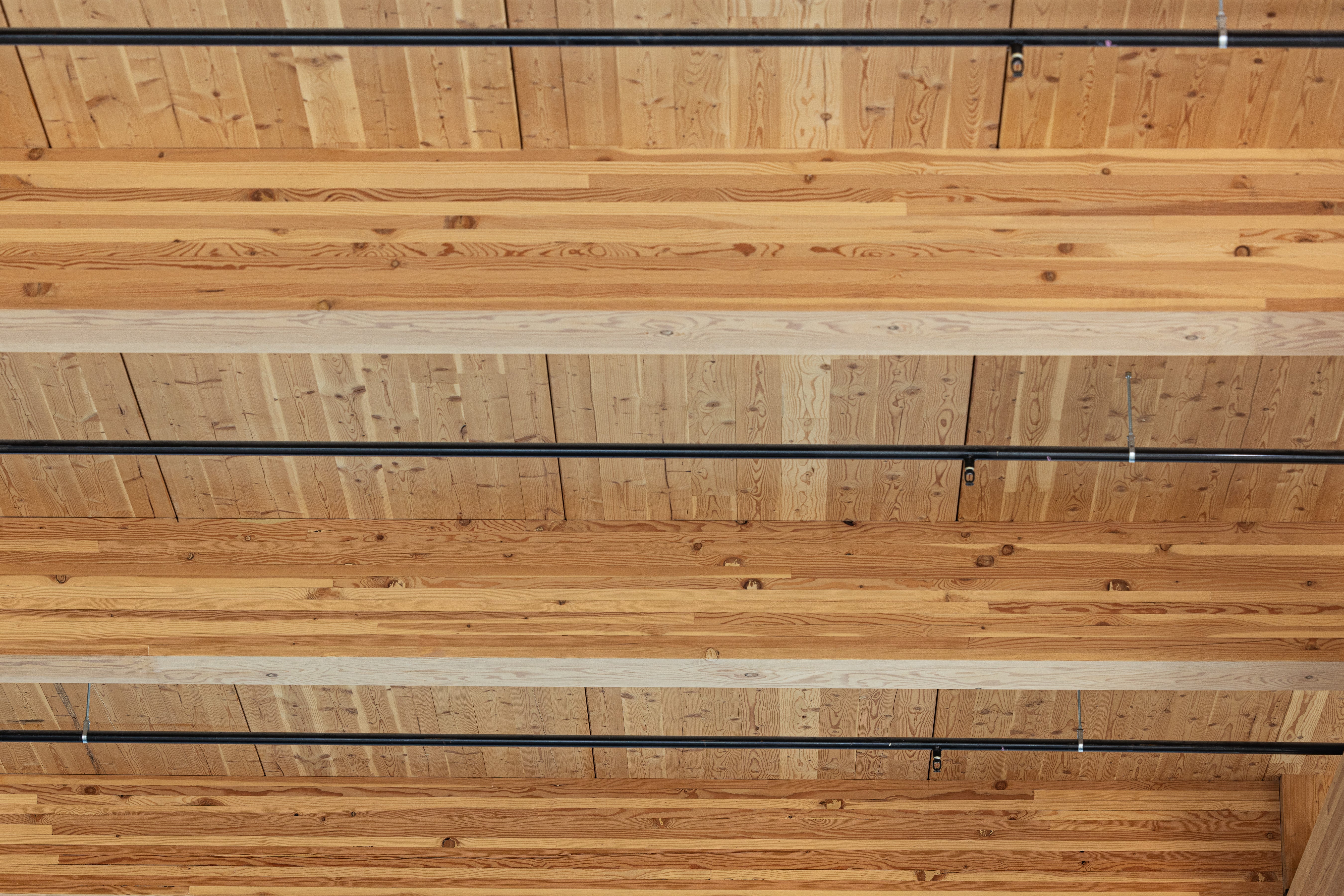
In the Pacific Northwest lab building, glulam posts, girders, and beams support thin cross-laminated timber (CLT) panels in a flush-frame configuration, reducing floor-to-floor heights and lowering envelope costs. To offset the reduced structural depth, stiffness was strategically increased in vibration-sensitive areas by providing additional beams, improving the overall floor stiffness while maintaining an efficient structural system.
Through sophisticated finite element method (FEM) modelling and detailed vibration analysis, the project team demonstrated that the stringent vibration criteria required for laboratory spaces could be achieved, illustrating what is achievable when these material factors are deliberately aligned.
Damping
Damping measures how quickly a vibrating system dissipates energy. In practical terms, it’s how fast floor vibrations fade. In buildings, dampening can be enhanced by non-structural elements such as furniture, finishes, and partition walls that absorb and disperse vibrational energy.
Unlike mass and stiffness, damping is difficult to predict analytically and is often estimated from testing or experience.
While mass, stiffness, and damping are foundational to floor performance, their role becomes even more critical in environments with stringent vibration requirements, such as laboratories and healthcare facilities. In these settings, the challenge is not just occupant comfort – but providing that sensitive equipment functions are reliable.
Meeting High Vibration Requirements in Labs and Hospitals
In commercial offices or residences, occupants are both the primary source and perceivers of vibration. Our perception and expectations around vibration are highly subjective, influenced by the sensitivity of our internal organs to certain frequency ranges, as well as factors like activity, body posture, and visual access to the vibration source. Human sensitivity typically lies between 4-8 Hz for vertical motion, and we generally cannot perceive changes in vibration amplitude smaller than 20%.
In contrast, labs and hospitals house equipment with precise vibration tolerances, where even minor floor movements can interfere with operations. In these environments, vibration performance is driven by functional need, not just comfort. Successfully mitigating vibration in these spaces requires close coordination between architectural planning, structural design, and engineering analysis — especially when using mass timber as a structural system.
Sources of Vibration in Labs & Hospitals
The most common sources of floor vibration are mechanical systems and human activity (such as walking). While these forces are typically low in magnitude, they can produce persistent vibration responses, especially in lighter and more flexible structural systems like mass timber. Although some sources of vibration — such as pedestrian traffic — cannot be eliminated, their effects can often be reduced through planning. Avoiding long, uninterrupted corridors that encourage faster walking speeds, separating busy circulation routes from vibration-sensitive spaces, and isolating vibration-producing mechanical equipment or sensitive instruments can all significantly reduce vibration demands. Combined with an optimized structural system, these strategies can substantially improve vibration performance without unnecessarily increasing material quantities or cost.
Vibration Requirement Comparison Across Occupancies
Vibration performance is typically quantified using a metric called RMS velocity, measured in micro-inches per second (mips). This performance is compared against Vibration Criterion (VC) curves, which are industry benchmarks developed for vibration-sensitive environments.
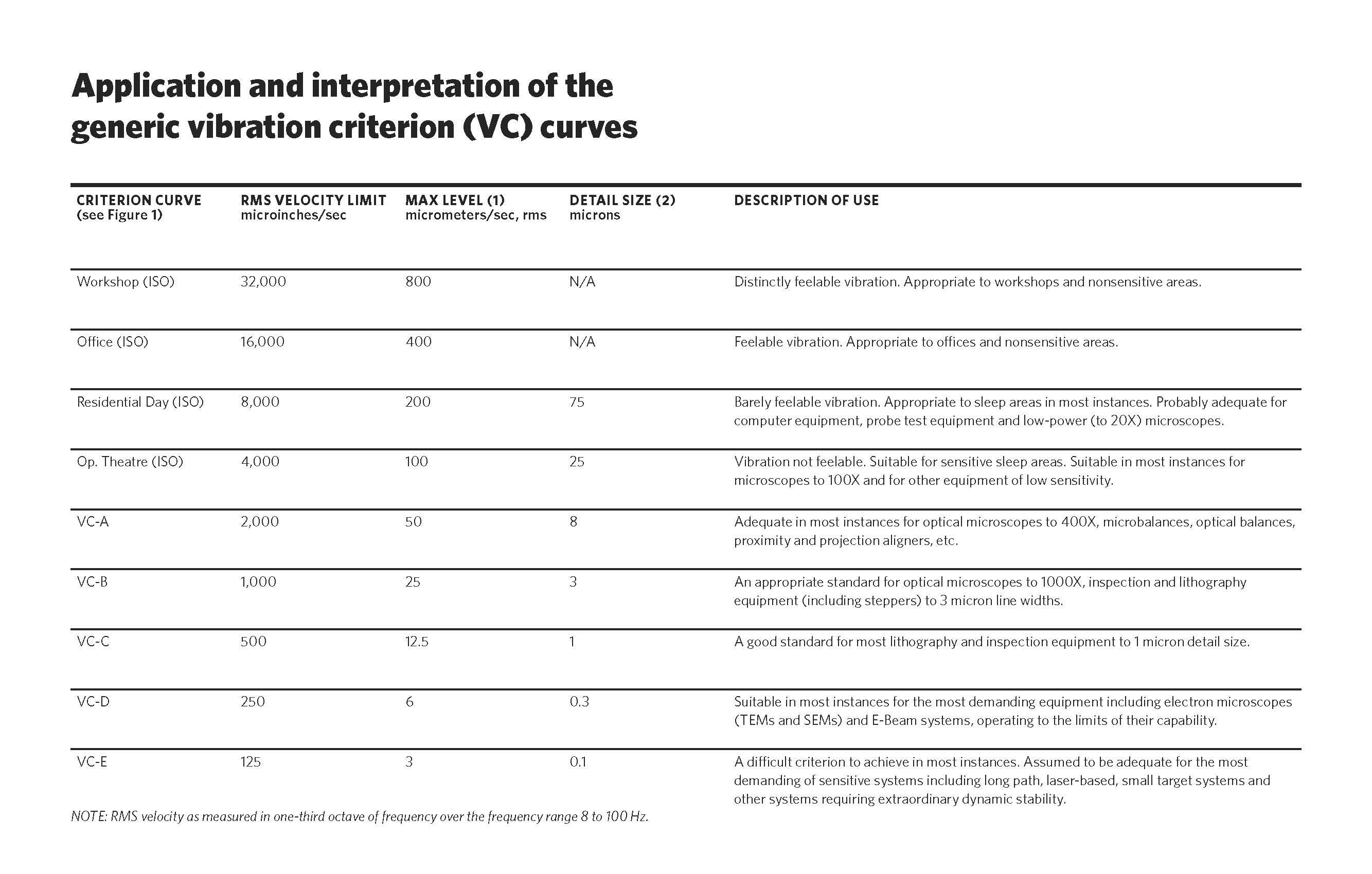
It's important to note that even with concrete construction, achieving VC-C, VC-D, or VC-E performance often requires slab-on-grade systems or even base isolation. For mass timber systems, we generally recommend avoiding applications with requirements more stringent than 2,000 mips. However, select projects demonstrate that, with intentional design, this threshold can be met.
One such example is a five-story science, technology, engineering and mathematics (STEM) building in the Midwest, designed as a hybrid mass timber building. The floor system consists of glulam posts, girders, and beams supporting thin CLT panels with reinforced concrete topping. To maximize floor stiffness while maintaining efficient service distribution, the girders are dropped and doubled along each grid line, while the beams are raised and closely spaced. The reinforced concrete topping serves multiple functions: it acts as the diaphragm transferring lateral loads to the steel cores, provides the required fire separation between floors, adds beneficial mass to the floor system, and works compositely with the timber framing through wood shear key connections, significantly increasing floor stiffness.
Preliminary analysis indicated that the framing could achieve the stringent VC-A vibration criterion across the entire floor plate. However, by strategically identifying areas requiring VC-A performance for vibration-sensitive equipment and designing the remaining open laboratory spaces to a 4,000 mips criterion, the design team optimized the structural system and reduced the timber volume by approximately 15% while still meeting the functional requirements of the building.
Spans and Layout Challenges
Lab and hospital layouts often use 11-foot planning modules, resulting in common grid spacings like 33 feet by 33 feet or 44 feet by 44 feet. These spans suit steel and concrete but challenge mass timber, which typically spans 20 feet to 30 feet. Designing a floor system that meets stringent vibration thresholds across long spans requires careful optimization of materials, framing strategy, and equipment layout.
Our team has designed and analyzed mass timber floor systems targeting performance levels of 6,000 mips, 4,000 mips and 2,000 mips. These solutions were developed using commercial FEM software and internally developed post-processing tools to predict vibration behavior. Success depends on a holistic approach — integrating architectural planning, structural strategy, mechanical/electrical/plumbing (MEP) coordination, and engineering judgment from the earliest stages of design.
Four Key Considerations in Achieving Vibration Performance
Meeting strict vibration criteria in mass timber lab or hospital floors requires a combination of strategies across multiple disciplines. We’ve found that successful projects share four key ingredients:
1. Thoughtful Architectural and Lab Planning
The earliest and often most critical opportunities lie in the building layout. Separating excitation zones (like busy corridors) from sensitive zones with tight vibration criteria can make a big difference. One effective strategy is to align corridors with adjacent column lines, where the floor tends to be stiffest and least responsive to footfall.
2. Thoughtful Structural Framing
When standard framing doesn't meet performance thresholds, design innovation is essential. Effective strategies include:
- Concrete topping on CLT panels to increase mass and two-way stiffness.
- Dropped girder-raised beam systems to enhance in-plane floor rigidity.
- Composite action between all floor elements — CLT, beams, and girders — with rigid connections for unified system behavior.
- Close beam spacing in equipment zones to locally increase stiffness.
- Full-height partitions that divide space and significantly increase damping.
We’ve explored hybrid systems combining CLT panels with steel framing, which have offered enhanced stiffness but with trade-offs in cost, complexity, and construction coordination due to the multiple trades.
3. Thoughtful Modeling and Analysis
Today, advances in modeling technology provide engineers with powerful tools to predict floor behavior more accurately. Typically, we use commercial FEM software for modal analysis, supplemented with custom post-processing tools to evaluate performance under realistic loading conditions.
Using these tools, we assess multiple mode shapes, modal masses, and natural frequencies, and subsequently conduct simulations of transient responses to walking patterns. Modern vibration assessments consider complete transient responses rather than relying solely on minimum natural-frequency limits. This detailed insight is crucial for evaluating performance at lower thresholds, like 2,000 mips. Due to the reliance on engineering judgment and available data, conducting sensitivity studies is essential to understand how variations in assumptions influence performance outcomes. Whenever possible, analytical predictions should be validated through field measurements on completed buildings.
4. Thoughtful Assumptions and Engineering Judgment
Code guidance for floor vibration is limited, especially for timber systems. Engineering judgment, internal research, and accumulated precedent play large roles in assessing performance. For example, assumed damping values (typically 2-4% for mass timber with concrete topping and full-height partitions) can significantly influence RMS velocity outcomes.
Even with advanced modeling, nuanced decisions — such as interpreting VC criteria, accounting for construction variability, or identifying dominant excitation modes — ultimately determine a floor's success. For example, lab buildings often require a two-hour rating for exposed mass timber. While extra fibers are often necessary for charring, they also inherently provide additional stiffness, benefiting vibration performance.
Conclusion
Mass timber should not be viewed as inherently unsuitable for vibration-sensitive facilities. Rather, it requires a different design philosophy— one that integrates architectural planning, structural configuration, advanced vibration analysis, and multidisciplinary coordination from the earliest stages of design. Achieving stringent vibration criteria requires more than sophisticated analytical tools; it depends on experienced engineers who understand the complex interaction between mass, stiffness, damping, structural layout, and architectural planning. When these considerations are addressed early, mass timber can successfully satisfy demanding vibration requirements while retaining its sustainability, constructability, and architectural advantages.
Figure A (Text Format)
Criterion Curve: Workshop (ISO)
RMS Velocity Limit; microinches/sec: 32,000
Max Level (1); micrometers/sec, rms: 800
Detail Size (2); microns: N/A
Description of Use: Distinctly feelable vibration. Appropriate to workshops and nonsensitive areas.
Criterion Curve: Office (ISO)
RMS Velocity Limit; microinches/sec: 16,000
Max Level (1); micrometers/sec, rms: 400
Detail Size (2); microns: N/A
Description of Use: Feelable vibration. Appropriate to offices and nonsensitive areas.
Criterion Curve: Residential Day (ISO)
RMS Velocity Limit; microinches/sec: 8,000
Max Level (1); micrometers/sec, rms: 200
Detail Size (2); microns: 75
Description of Use: Barely feelable vibration. Appropriate to sleep areas in most instances. Probably adequate for computer equipment, probe test equipment and low-power (to 20X) microscopes.
Criterion Curve: Op. Theatre (ISO)
RMS Velocity Limit; microinches/sec: 4,000
Max Level (1); micrometers/sec, rms: 100
Detail Size (2); microns: 25
Description of Use: Vibration not feelable. Suitable for sensitive sleep areas. Suitable in most instances for microscopes to100X and for other equipment of low sensitivity.
Criterion Curve: VC-A
RMS Velocity Limit; microinches/sec: 2,000
Max Level (1); micrometers/sec, rms: 50
Detail Size (2); microns: 8
Description of Use: Adequate in most instances for optical microscopes to 400X, microbalances, optical balances, proximity and projection aligners, etc.
Criterion Curve: VC-B
RMS Velocity Limit; microinches/sec: 1,000
Max Level (1); micrometers/sec, rms: 25
Detail Size (2); microns: 3
Description of Use: An appropriate standard for optical microscopes to lOOOX, inspection and lithography equipment (including steppers) to 3 micron line widths.
Criterion Curve: VC-C
RMS Velocity Limit; microinches/sec: 500
Max Level (1); micrometers/sec, rms: 12.5
Detail Size (2); microns: 1
Description of Use: A good standard for most lithography and inspection equipment to1micron detail size.
Criterion Curve: VC-D
RMS Velocity Limit; microinches/sec: 250
Max Level (1); micrometers/sec, rms: 6
Detail Size (2); microns: 0.3
Description of Use: Suitable in most instances for the most demanding equipment, including electron microscopes (TEMs and SEMs) and E-Beam systems, operating to the limits of their capability.
Criterion Curve: VC-E
RMS Velocity Limit; microinches/sec: 125
Max Level (1); micrometers/sec, rms: 3
Detail Size (2); microns: 0.1
Description of Use: A difficult criterion to achieve in most instances. Assumed to be adequate for the most demanding of sensitive systems, including long path,laser-based, small target systems and other systems requiring extraordinary dynamic stability.


