
Semiconductor Facility Design Optimization
While global events have certainly changed the short-term outlook, fairly steady growth in micro-electronics capital expenditure is expected well into the next decade. In 2019, microelectronics sales revenue was about $400 billion and prior to the COVID-19 pandemic, was expected to grow 5% from 2019 to 2020 (approximately $20B). This ever increasing demand for computer chips has driven semiconductor manufacturer’s capital expenditure to increase from approximately $10B in 2015 to approximately $20B in 2019. While the full impact of the pandemic is yet to be seen, preliminary forecasts predict a reduction in unit sales of roughly 3% in 2020 (Source IC Insights), but for steady growth to return in early 2021.
With any growth in unit sales, there will be a commensurate growth in semiconductor companies’ capital expenditures across the following three buckets: process tools, the base facility (building and utility systems) and the process tool installation. Of the three, capital cost of the process tools is by far the largest, at about 65% of the total. Base facility cost is next at about 30% and tool hookup at around 5% (depending on where you draw the line between base facility and hookup).
To reduce the capital cost of the base facility, integrated circuit manufacturers are challenging the A&E community to find ways that the fabrication facility and utility systems can be built faster and at lower cost. Optimizing the location of the facility's equipment relative to the manufacturing floor and optimizing the utility routing (conveyance) strategies are areas with significant untapped potential.
Location Matters: Re-Evaluating Fab Site Placement
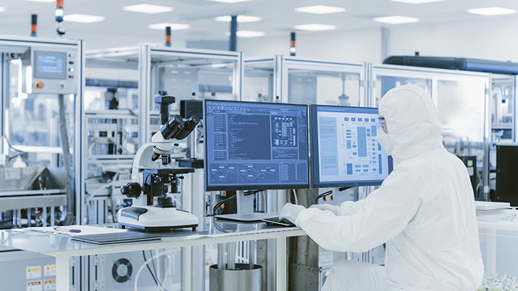
The concept of optimizing resources is not new to IC manufacturers who are frequently looking for better ways to improve the process equipment’s down, idle and queue times. For example, fab operators use manufacturing modeling software to optimize the placement of process tools within the cleanroom to derive benefits such as reducing tool wait time or reducing product transportation time. The same idea can be applied to the base building component placement on the site.
The Typical “Outside-In” Approach
The typical approach to placing the fab and the central utility building on a site is “outside-in” based on a previously developed site master plan that is primarily informed by how the last fab was configured and which primarily considers outside constraints such as property lines, where utilities are entering the site and surrounding traffic patterns. Another common tactic is to put all facilities equipment that are not in the fab building into one large CUB.
An Alternative “Inside-Out” Approach
A better approach may be to design things from the “inside-out.” Start with defining where the fab processing functional areas will be located within the cleanroom. Then note which of these functional areas are the largest consumers of a given facility system. For example, the deposition and dry etch areas use by far the most specialty gases but use relatively low levels of ultrapure water, whereas the wet clean/etch area uses the vast majority of UPW and wet chemicals and also a significant amount of the exhaust totals.
Here at HDR, we pair this information with our Data Driven Design tools to digitally model hundreds of different possible facility system placements within the building and on the site to quickly identify the top few options which have the lowest cost of conveying the utility system between the source and the major use point in the fab. These options, by definition, would also have the simplest utility space plan and would require the lowest amount of field labor to erect. While the cost of conveyance should not be the ONLY consideration for site placement, it should be a key consideration. This approach provides valuable data to help better understand that cost.
Lessons from Cost of Conveyance Studies
One of the interesting findings from running these types of analyses: the specialty gas dispense rooms often wants to be on a different side of the building than the wet chemical dispense rooms. This may drive the need for two different hazardous production material delivery docks but would result in much shorter delivery line lengths, faster and lower cost installation, and reduced utility routing congestion.
Another interesting finding is that the location where a given utility service would ideally enter and/or leave the fab building can be different from the other services. For example, in one prior example, construction costs were reduced if the chilled and hot water supply and return lines entered the fab building on its short end, but the UPW and drains entered/left the wafer fab in the middle of one of its long sides. This logically lead to proposing that the boiler/chiller CUB be different than the UPW makeup building which was different than the wastewater treatment building. Each building could then be tailored (column spacing, ceiling heights, etc.) to the facility equipment’s needs. In one of my previous projects, this led to much simpler CUB building structures including a butler style building and containerized/modularized facility systems.
Achieving Cost and Schedule Savings
Two of my previous projects demonstrated that significant cost and schedule savings can be achieved if this type of study is conducted early in the fab design process. Both examples (one from 5 years ago for a U.S. based company and one from last year for a company in Asia) showed that savings of more than 10% of the base build capital cost can be achieved by optimizing the facility system placement, right-sizing the facility spaces, reducing the length of utility conveyance, simplifying utility space management and simplifying the CUBs structure.
The best way to conduct these types of studies is through the use of digital analytical tools. The next article in this series will dive deeper into what some of those tools are, how they work, and how they can be effectively applied to fab building and utility system design.